|
"Most holes will have both a size
and position tolerance. This combination causes the hole to
"act" larger and smaller than the actual size from a fit and
shift stand point. The smallest the hole may act is called the
inner boundary. The largest the hole may act is called the
outer boundary. The inner boundary represents the closest the
surface of the hole may ever get to the basic location
relative to the referenced datums. This boundary often affects
the fit of mating parts. The outer boundary represents the
farthest the surface of the hole may ever get from the basic
location relative to the referenced datums. This boundary
often affects the shift or slop between mating parts. The
dynamic tolerancing diagrams illustrated below show how the
boundaries are affected when position and profile tolerances
are applied to a hole. The solid area indicates all of the
tolerance of both size and position (including bonus tolerance
allowed by modifiers) allowed on the hole. The blue area in
each example shows the allowable tolerance when position at
RFS is used. The green areas show additional or bonus
tolerance."
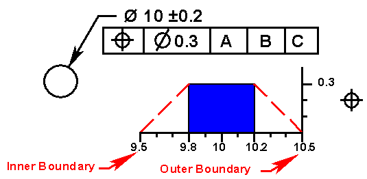
In this first example Regardless of
Feature Size is implied. This is the most restrictive
(expensive) control. Although the size may not be less than
9.8mm or greater than 10.2mm, the hole may act like 9.5mm to
10.5mm. Any holes made from 9.5mm to 9.8mm or from 10.2mm to
10.5mm should be rejected for size even though they may
function.
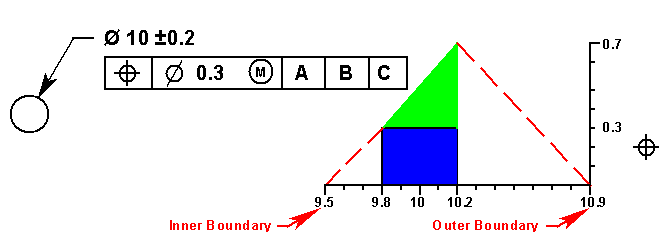
By using the MMC modifier, a bonus
is allowed that could permit the hole to be out of position by
as much as 0.7mm. Although the inner boundary did not change,
the outer boundary has grown to 10.9mm since a 10.2mm size
hole may be out of position by as much as 0.7mm due to bonus
tolerance. This could cause shift problems if this hole is
being used to locate parts in an assembly.
 |
|

|
|
By using the LMC
modifier, a bonus is allowed that could once again
permit the hole to be out of position by as much as
0.7mm. This time the outer boundary did not change from
the first RFS example, but, the inner boundary could be
as small as 9.1mm since a 9.8mm size hole may be out of
position by as much as 0.7mm due to bonus tolerance.
This could cause fit problems in an
assembly. |
|

|
|
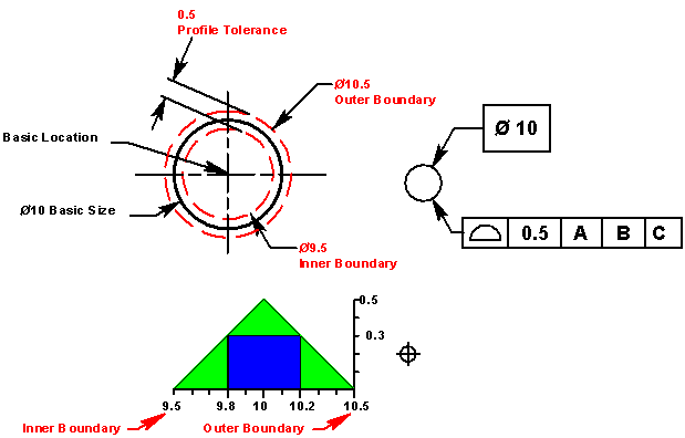
Although
historically profile of a surface has not been widely
used to locate holes, it is acceptable and offers many
advantages. When the size and locating dimensions are
basic, profile controls both size and position. The
green areas represent the additional tolerance realized
if profile rather than position at RFS is used. The
closer to 9.5mm or 10.5mm production makes the hole, the
better the position of the hole must be. Production is
given the greatest position allowance of 0.5mm if they
produce holes at 10mm. This gives production the most
possible tolerance while protecting both the inner and
outer boundaries. It also encourages production to keep
their process centered at 10mm. Designers often use
position at MMC for holes because it provides bonus
tolerance while assuring fit between mating parts. What
they often miss is the resulting shift that may occur
between mating parts. Using profile of a surface in this
manner provides the most tolerance while protecting an
assembly's fit and shift. |
 | |