Datum references in the second segment of
a composite feature control frame tighten the orientation of
the
pattern-no matter what the angle.
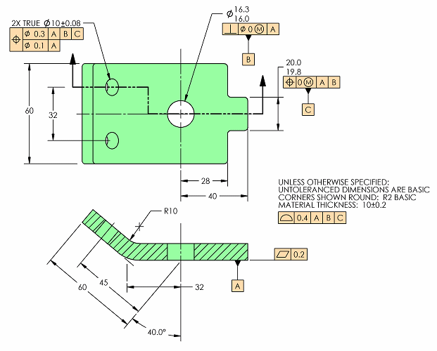
Here is a Tip inspired by one of
our regular readers of the Tips. He pointed out that in the
examples of composite tolerancing in the Y14.5 standard that
explain the meaning of a datum reference in the second
segment, the pattern of features seems to always be
conveniently oriented squarely to the datum reference frame.
His question was, "What if the pattern is at a compound angle
to the datum reference framework?" Well, it doesn't matter
what angle the pattern is from the datum reference frame. Any
datum reference in the second segment of a composite feature
control frame tightens up the orientation of the pattern. Of
course, the other purpose of the tolerance in the lower
segment is to tighten the location of the features in the
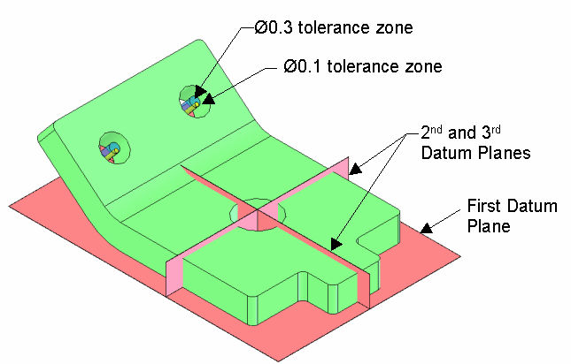
pattern to one another. In this example, the tolerance zones
of the composite callout are shown in blue and yellow in the
isometric views.t, they refine the orientation
(perpendicularity, parallelism or angularity) of the pattern
relative to the referenced
datums.
|